10+ spi block diagram
The main function of UART is to serial data communication. Driving Lamps - Cooper SPi Headlamp Assembly-From V 134455 Headlamp Assembly- LHD-Germany Headlamp Assembly-LHD-To V 134454.
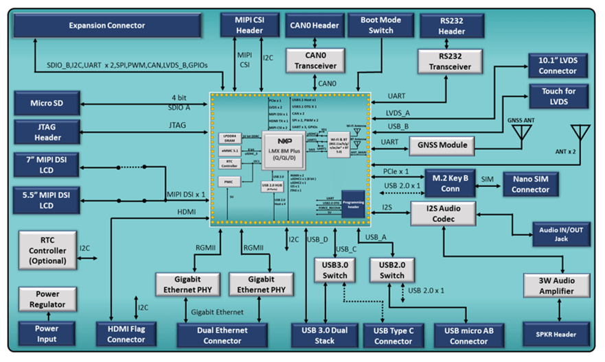
I Mx 8m Plus Pico Itx Sbc Iwave Systems
SPIx Module Block Diagram Standard Mode Internal Data Bus SDIx SDOx SSxFSYNCx SCKx bit 0 Shift Control Primary FP 1141664 Enable Prescaler Sync SPIxBUF Control Transfer Transfer Read SPIxBUF Write SPIxBUF 16 SPIxCON1 SPIxCON1 Master Clock Clock Control Secondary.
. The microprocessor unit MPU subsystem is based on the ARM Cortex-A8 processor and the PowerVR SGX Graphics Accelerator subsystem provides 3D graphics acceleration to support display and gaming effects. 24- or 32-bit address options. SPI Multi-IO 30 V Logic block diagram Logic block diagram Performance summary Maximum read rates with the same core and IO voltage V IO VCC 27 V to 36 V Command Clock rate MHz MBps Read 50 625 Fast Read 133 166 Dual Read 104 26 Quad Read 104 52 Maximum read rates with lower IO voltage V IO 165 V to 27 V VCC 27 V to 36.
This article discusses what UART How UART Works the difference between serial and parallel communication UART block diagram UART communication UART interfacing Applications. A simple block diagram of the MCP2515 is shown in Figure 1-1. Avoid using these pins as it may disrupt access to the SPI flash memory SPI RAM.
The contains the subsystems shown in the Functional Block Diagram and a brief description of each follows. Block diagram of SC16IS750760 I2C-bus interface Fig 2. When the data byte is successfully transmitted an interrupt signal is generated which may help you for starting or waiting before another data transaction process.
Over 20 different CAD formats are supported offering consistent symbols. The SPI protocol block. The 2 SPI devices will be 2 4131 digital potentiometers.
Single UART with I2C-busSPI interface 64-byte FIFOs IrDA SIR 5. MachXO3 Family Data Sheet - Lattice Semi. SPI Block Guide V0401 13 Section 1 Introduction Figure 1-1 gives an overview on the SPI architecture.
So when a chips timing diagram shows the clock starting low CPOL0 and data stabilized for sampling during the trailing clock edge CPHA1 thats SPI mode 1. Serial Peripheral Interface SPI Module Figure 1-1. High speed SPI interface 32 MHz RAM mapped FIFO using EasyDMA 12 bit 200K SPS ADC I28 bit AESECBCCMAAR co-processor Single-ended antenna output on-chip balun Programmable peripheral interconnect PPI Quad SPI interface 32 MHz EasyDMA for all digital interfaces On-chip DC-DC buck converter.
3V3 and GND pin headers. In UART the communication between two devices can be done in two ways namely serial data. ETQFP48 7x7 QFN56 8x8 wettable flank.
The control logic and registers that are used to configure the device and its operation. Note that the clock mode is relevant as soon as the chipselect goes active. Block diagram of SC16IS740 I2C-bus interface SC16IS750760 16C450 COMPATIBLE REGISTER SETS 002aab014 VDD I2C-BUS TX RX RTS GPIO REGISTER CTS GPIO30 XTAL1 XTAL2 SCL SDA A0 IRQ I2CSPI 4 A1.
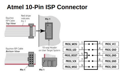
Header Block The two tables. The MSb is shifted out first followed by the rest of the 8-bit data frame. 5V and GND pin headers.
In the SPI mode number CPOL is the high order bit and CPHA is the low order bit. 2 MCP4231 Digital Potentiometer. We will show how this is actually hardwared together.
We will wire these 2 SPI potentiometers to the arduino and show how the arduino can control them. Block Diagram Pinout. The CAN module which includes the CAN protocol engine masks filters transmit and receive buffers.
Block Diagram TMC5160 Pinout TMC5160A-TA Pinout TMC5160A-WA Integration Made Easy. You can now easily identify this functionality by carefully following the SPI hardware block diagram. In simple terms it is a mover.
The main parts of the SPI are statuscontrol and data registers shifter logic baud rate generator masterslave control logic and port control logic. An actuator requires a control device controlled by control signal and a source of energyThe control signal is relatively low energy and may be electric voltage or current pneumatic or. In this circuit we will connect 2 SPI devices to an arduino microcontroller.
Block Diagram The block diagram below shows the components of ESP32-C3-DevKitM-1 and their interconnections. The Serial Peripheral Interface SPI is a synchronous serial communication interface specification used for short-distance communication primarily in embedded systemsThe interface was developed by Motorola in the mid-1980s and has become a de facto standardTypical applications include Secure Digital cards and liquid crystal displays. ESP32-C3-DevKitM-1 click to enlarge Power Supply Options There are three mutually exclusive ways to provide power to the board.
1990 and Later Mini Diagram Catalog Chapter 1 - Engine Chapter 2 - Flywheel Clutch Chapter 3 - Gearbox Gear Train Chapter 4 - Driveshafts Suspension and Wheels. SPIUART MSP430F1132 8. Block diagram Fig 1.
O To. An actuator is a component of a machine that is responsible for moving and controlling a mechanism or system for example by opening a valve. The device consists of three main blocks.
Speed up your workflow by downloading all the CAD symbols you need. 3 12 The pins GPIO16 and GPIO17 are available for use only on the boards with the modules ESP32-WROOM and ESP32-SOLO-1. Micro-USB Port default power supply.
101 Introduction 148 102 SPI Master Mode 148 1021 Standard mode 148 1022 Bidirectional mode 149 103 LoSSI mode 150 1031 Command write 150 1032 Parameter write 150 1033 Byte read commands 151 1034 24bit read command 151 1035 32bit read command 151 104 Block Diagram 152 105 SPI Register Map 152 106 Software Operation 158 106. With a CAN bus.

0 96 80 X 160 Full Color Ips Lcd Module Pmd Way

10 Multiple Effect Evaporator Diagram Of Multiple Effect Evaporator Pharmacy Images Medicine Images Free Human Body

2 42 128 X 64 White Oled Display Spi Pmd Way

Web Spinner Knitting Patterns Boys Boys Knitting Patterns Free Knitting Patterns

10 Panasonic Car Radio Wiring Diagram Sony Car Stereo Panasonic Car Audio Car Stereo

Dh Electronics Dhcom Stm32mp15

Intel Arria 10 Soc System On Modules Iwave Systems Mouser

Odyssey Mini Pc X86j4125 Ameridroid

Agilex R31b R31c Soc Fpga Som Iwave Systems
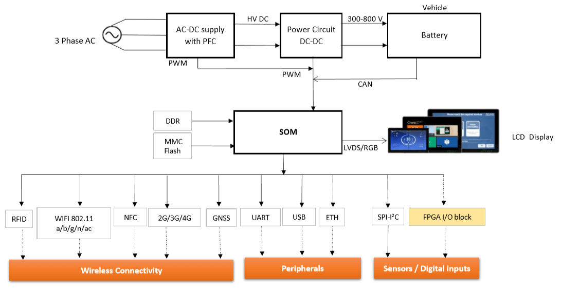
Advanced And Scalable Som Hmi Solutions For Ev Charging Station Iwave Systems
The Atmega328p From Almost Nothing

Adas1000 2 Datasheet And Product Info Analog Devices

Adas1000 Datasheet And Product Info Analog Devices

Arduino Nano Pinout Diagram And Specifications Etechnog
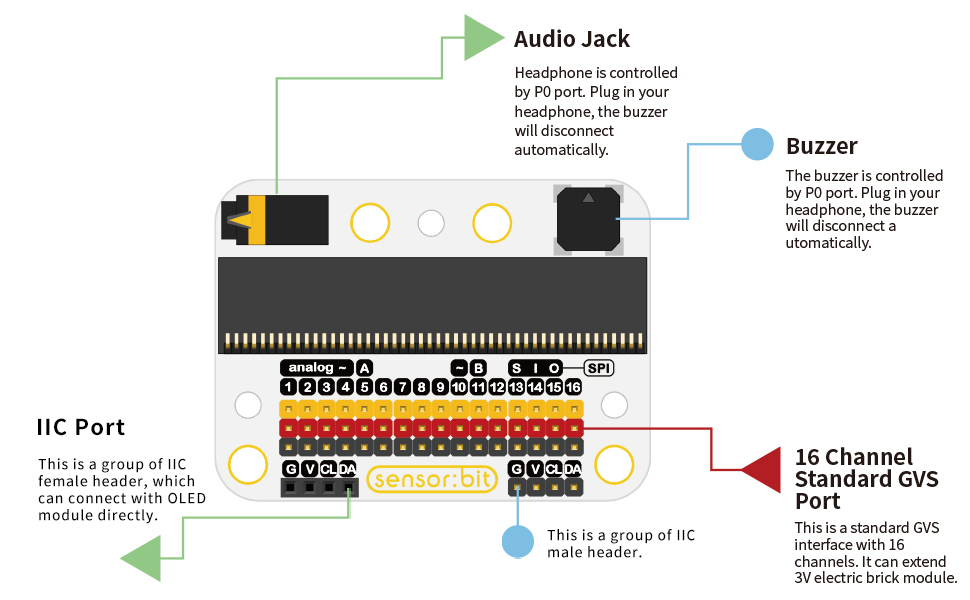
Amazon Com Elecfreaks Microbit Smart Home Kit For Kid Micro Bit Sensor Starter Kit Octopus Series Sensor Diy Programming Stem Kit With Basic Coding Electronics Modules And Wiki Tutorial Without Micro Bit Electronics
I Mx 8m Plus Smarc Som Iwave Systems
Jsan Free Full Text Control Of Power Electronics Through A Photonic Bus Feasibility And Prospects Html